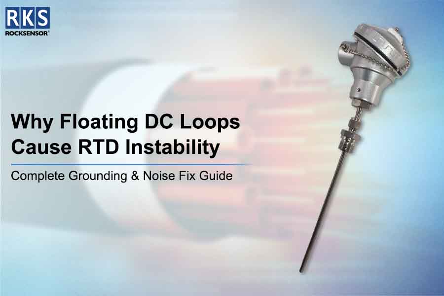
Why Floating DC Loops Cause RTD Instability
RTDs serve as critical instruments that measure temperature with high accuracy throughout industrial operations. Engineers face difficulties with temperature measurements because certain readings experience unpredictable changes. The main reason? The system experiences problems because it contains floating DC loops and inadequate grounding between components and electrical noise. The guide explains how floating loops create RTD instability and offers methods for stabilizing RTD signals through grounding and noise elimination techniques.
Understanding RTD Instability in Industrial Applications
The accuracy and long-term stability of RTDs serve as their main advantage. The presence of industrial signal interference together with electrical noise in actual environments creates measurement distortion problems. The sensor shows wrong temperature readings because stray voltages and ground loops interfere with the RTD connection through a floating DC loop.
A floating loop exists when the measurement circuit operates without any connection to the system ground. The practice of grounding measurement circuits may create problems that operators use to eliminate, but it results in temperature sensor noise and RTD signal drift that disrupt process control.
Signs Your RTD May Be Affected by Floating Loops
- Fluctuating temperature readings
- Delayed response to actual temperature changes
- Gradual drift in readings over time
Floating loops are particularly sensitive to EMI interference in RTDs and industrial sensor noise, often caused by nearby motors, drives, or communication lines.
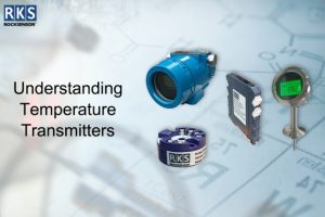
For accurate industrial temperature measurements, explore our Temperature Transmitters designed to reduce RTD signal drift.
What is a floating DC loop?
A floating DC loop is a circuit configuration where the RTD sensor isn’t directly referenced to a system ground. This isolation can be beneficial in some scenarios, but for RTDs, it often leads to unstable readings.
Why Proper Grounding Reduces RTD Instability
Proper RTD grounding techniques are critical for maintaining accurate temperature measurements. Grounding protects the RTD signal by stopping stray voltages from entering the system. The sensor experiences a floating effect when multiple grounding points or improper grounding methods are used.
Effective Grounding Methods
- Single-Point Grounding: The RTD system needs one main reference point to prevent ground loop problems.
- Shielded Twisted-Pair Cables: The use of shielded cables protects against electromagnetic interference which can affect other equipment.
- Isolated Transmitters: The transmitter needs to be disconnected from the main power supply because this protects the loop from noise interruption.
The measurement systems will experience lower RTD instability together with reduced temperature sensor noise through the application of these techniques. With these techniques, you can significantly reduce RTD instability and temperature sensor noise in your measurement systems.
How Electrical Noise Causes RTD Instability
Electrical noise can mimic real temperature changes, making an RTD appear unstable. Common RTD noise sources include:
- Motors and variable frequency drives (VFDs)
- High-power switching devices
- Nearby communication and power cables
The RTD signal experiences noise through spikes and oscillations, which demonstrate a reduction when controlled shielding and proper grounding and loop isolation techniques are implemented.
A step-by-step process enables users to correct the floating DC loop system which exhibits instability issues.
This guide provides practical steps that help you achieve stable RTD measurements and complete RTD signal drift elimination.
Step 1: Inspect the Circuit
You should determine whether your RTD loop system operates in a floating state or establishes unintended connections with several ground networks.
Step 2: Apply Proper Grounding
Single-point grounding should be implemented because it stops ground loops while providing a constant reference voltage.
Step 3: Shield and Route Cables
The installation of shielded twisted-pair cables requires protection from industrial sensor noise by maintaining distance from high-power equipment.
Step 4: Filter High-Frequency Noise
The installation of low-pass filters or RC snubbers will decrease electrical interference in the system.
Step 5: Use Isolated Transmitters if Needed
The isolated RTD transmitter separates the sensor system from system noise when instability continues to occur.
Common Installation Mistakes Leading to RTD Instability
- Connecting multiple ground points creating ground loops
- Using unshielded cables near motors, drives, or high-power devices
- Ignoring EMI interference in RTDs
- Using floating DC loops without considering industrial electrical environments
Pro Tip: Conduct a plant noise survey before installation to identify potential interference sources.
FAQs
Can a floating RTD loop ever be stable?
Yes, but it requires careful isolation, shielded cables, and a controlled electrical environment.
How does grounding reduce RTD signal drift?
Grounding gives the circuit a stable reference voltage, ensuring that stray currents are unable to influence readings.
What type of cable is best for RTD installations?
Twisted-pair shielded cables minimize noise pickup and reduce industrial signal interference.
Why do RTDs near motors show unstable readings?
Motors generate strong electromagnetic fields that induce voltages in nearby RTD circuits, causing RTD instability.
Can filters alone fix RTD noise issues?
Filtering helps but cannot replace proper grounding, shielding, and loop isolation.
Conclusion
Floating DC loops are a hidden source of RTD instability. The temperature measurements will achieve accurate results when you implement shielded cables and grounding methods and decrease industrial sensor interference.
The RTD readings will remain stable through these steps while your process control will improve and you will experience fewer maintenance issues from signal drift and electrical interference.